In the following tutorial you will learn to create a Computer Mouse by using some basic tools, the Pathfinder palette, vector shape building techniques, gradients, duplicated shapes and more.
Final Image
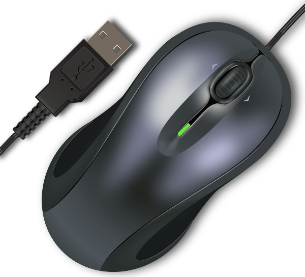
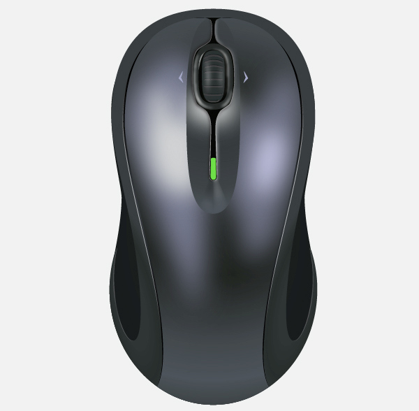
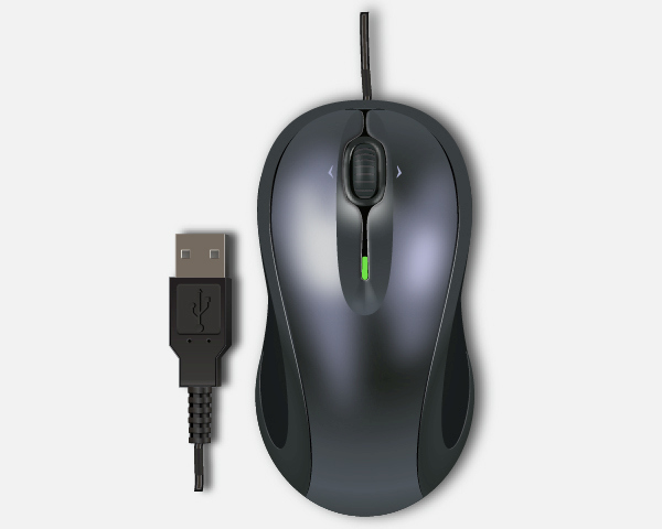
As always, this is the final image that we’ll be creating:
Tutorial Details
- Program: Adobe Illustrator CS6
- Estimated Completion Time: 60 minutes
- Difficulty: Beginner-Intermediate
Step 1
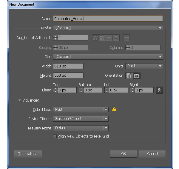
Launch Illustrator and then press (Ctrl + N) to create a New document. Select Pixels from the Units drop-down menu, enter 610 in the width box and 550 in the height box then click on the Advanced button. Select RGB, Screen (72ppi) and make sure that the Align New Objects to Pixel Grid box is unchecked before you click OK.
Step 2
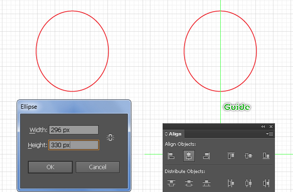
Start with drawing a 296 by 330px object using the Ellipse Tool (L).
Next show the Rulers (View > View Rulers > Show Ruler) or (Ctrl +R). Next drag a vertical guide from the Rulers (if the guide is locked, go to the View > Guides > Lock Guides) or (Ctrl +Alt + ;). Now reselect this guide and the ellipse, then open the Align palette (Window > Align) and click on the Horizontal Align Center button.
Step 3
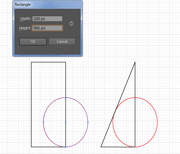
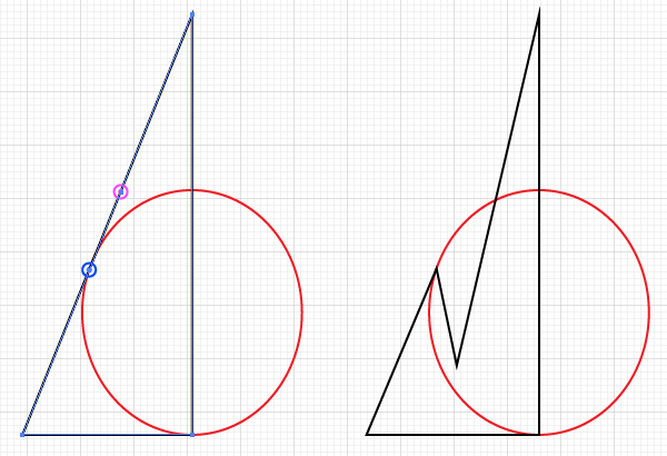
With the help of the Rectangle Tool (M) create a 228 by 566px object and then place it in the correct position as shown below.
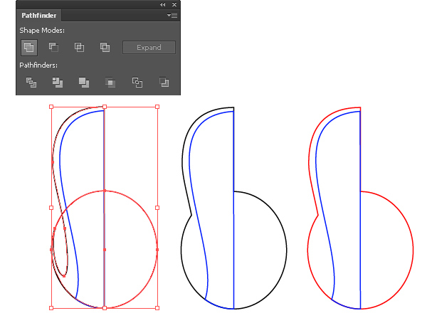
Next select the top-left anchor point of the new object and remove it. Now pick the Add Anchor Point Tool (+) and add two anchor points highlighted with magenta and blue, then move the anchor point highlighted with magenta to the position like you see in the final image below.
Step 4
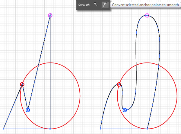
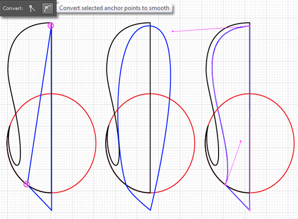
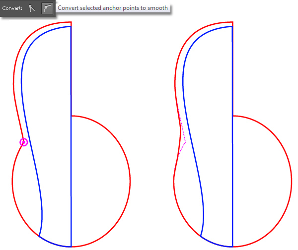
Select the three anchor points highlighted with magenta, red and blue of the new object and then click on the "Convert selected anchor points to smooth" button from the Properties bar.
Next pick the Convert Anchor Point Tool (Shift +C) and use this tool to adjust the handles of the anchor points as you see in the third image below.
Step 5
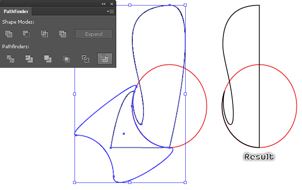
Select the red ellipse and duplicate (Ctrl +C, Ctrl +F) it once. Replace the existing stroke color of the copy with blue and then add an anchor point highlighted with magenta.
Now pick the Direct Selection Tool (A), hold down the Shift and select the two anchor points highlighted with red. Next release the Shift, click on the point highlighted with black and drag the mouse in the direction of the arrow to get the result as shown in the third image.
Now reselect the just edited object and the black object created in step 4, then open the Pathfinder palette (Window > Pathfinder) and click on the Minus Back button.
Step 6
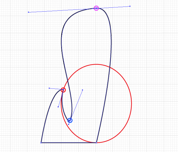
With the Pen Tool (P) create a blue object as shown below. Once your object is drawn, select the two anchor points highlighted with magenta and click on the "Convert selected anchor points to smooth" button from the Properties bar.
Next use the Convert Anchor Point Tool (Shift +C) to adjust the handles of anchor points of the blue object. In the end your blue object should look like the third image shown.
Step 7
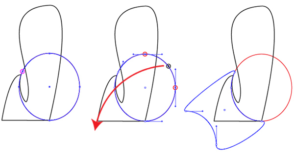
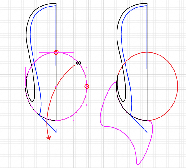
Select the red ellipse and make a copy of it (Ctrl +C, Ctrl +F), then replace the existing stroke color of the copy with magenta.
Now pick the Direct Selection Tool (A), hold down the Shift and select the two anchor points highlighted with red. Next release the Shift, click on the point highlighted with black and drag the mouse in the direction of the arrow to get the result as shown in the second image.
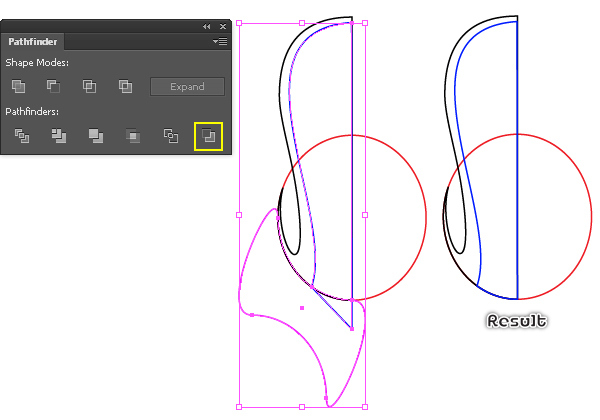
Now reselect the just edited object and the blue object created in step 6, then open the Pathfinder palette (Window > Pathfinder) and click on the Minus Back button.
Step 8
Select the black object and make a copy (Ctrl +C, Ctrl +F) of it, then hide the copy (Ctrl +3).
Reselect the black object and the red ellipse and then click on the Unite button from the Pathfinder palette.
Next replace the existing color of the resulting object with red. Now select the anchor point highlighted with magenta of the new object and click on the "Convert selected anchor points to smooth" button from the Properties bar.
Next adjust the handles of this anchor point to get the result as you see in the final image below.
Step 9
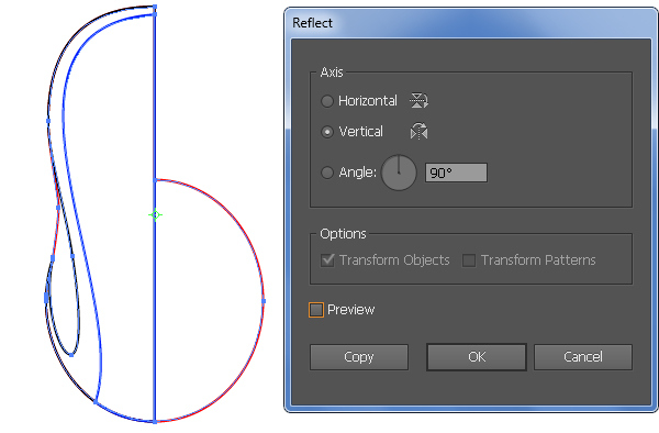
Press (Ctrl +Alt +3) to show the object hidden in the previous step.
Next select all objects created from the beginning of step 2 to this time and double-click on the Reflect Tool. In the Reflect box, check the Vertical and then click Copy, then move the copies 1px to the left.
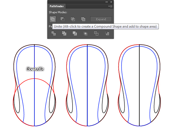
Now select the two red objects, open the Pathfinder palette (Window > Pathfinder) and click on the Unite button.
Next select the two blue objects and click on the Unite button from the Pathfinder palette.
Step 10
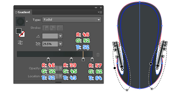
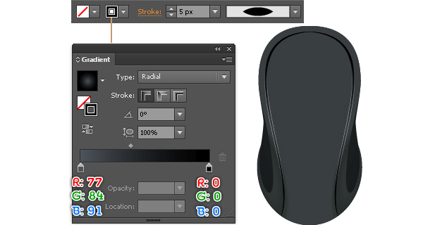
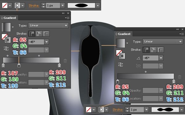
Fill the two black objects with the radial gradient as shown in the first image.
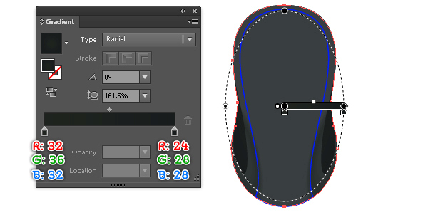
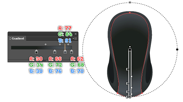
Next fill the red object with the radial gradient as you see in the second image.
Step 11
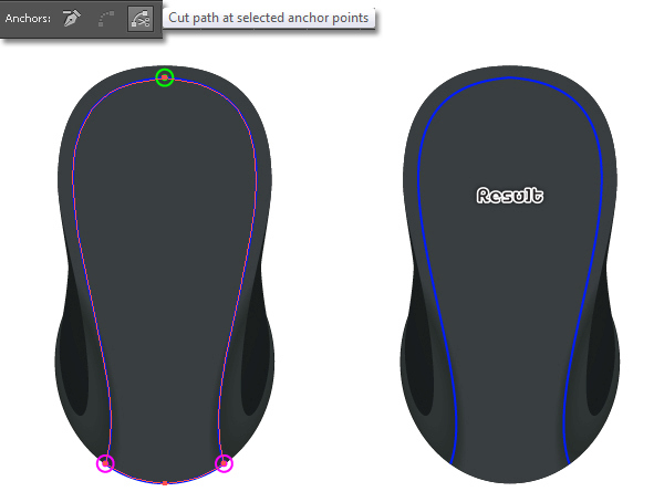
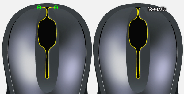
Select the blue object, duplicate it once and then hide the copy. Next select the three anchor points highlighted with green and magenta of the remaining blue object, then click on the "Cut path at selected anchor points" button from the Properties bar and remove the bottom path.
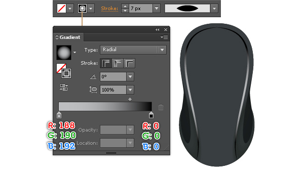
Now select the two remaining blue paths, fill them with none and add a 7px stroke (apply the radial gradient within the stroke), then apply the Width Profile 1 for the results.
Make a copy (Ctrl +C, Ctrl +F) of two new objects. Replace the existing stroke color of the copies with a new radial gradient and change the stroke weight to 5px.
Step 12
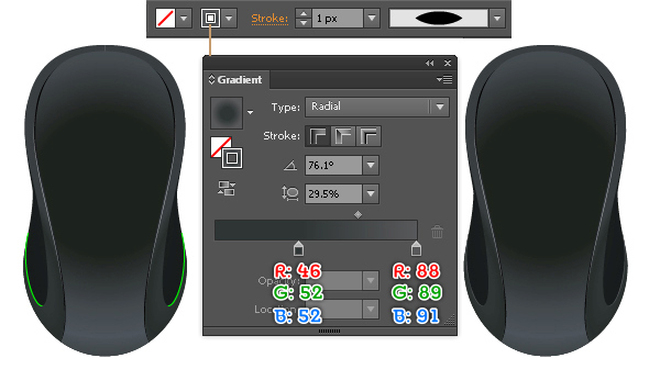
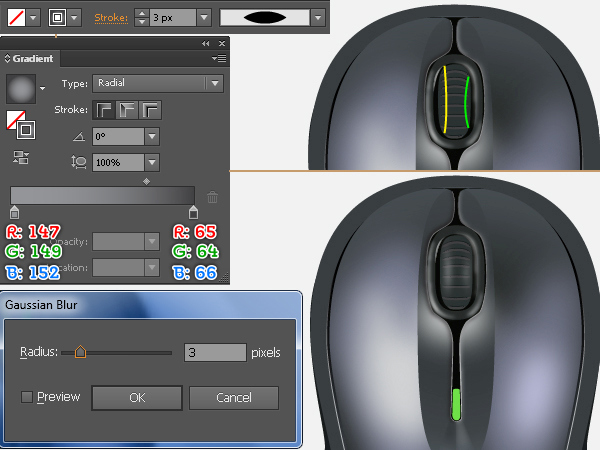
Press (Ctrl +Alt +3) to show the object hidden in step 11 and then fill it with the radial gradient as shown below.
Step 13
To add some details, first draw two curved paths with the help of the Pen Tool (P). Once your paths are drawn, fill them with none and add a 1px stroke (apply the radial gradient within the stroke), then apply the Width Profile 1 for the results.
Step 14
We are going to start making highlights on the computer mouse to give it more of a 3D look.
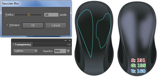
First draw two objects as shown below and then fill them with R=131, G=135, B=160.
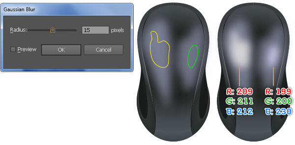
Keep the resulting shapes selected, go to the Effect > Blur > Gaussian Blur… Enter a 18px Radius and then click OK.
Make sure that the resulting shapes are still selected, open the Transparency palette (Window > Transparency), set the Blending Mode to Lighten and reduce the Opacity to 90%.
Continue to create two other objects as shown in the third image. Once your objects are drawn, fill the yellow object with R=209, G=211, B=212 and then fill the remaining object with R=199, G=200, B=230.
Reselect the two newly created shapes and apply a 15px Gaussian Blur effect to them.
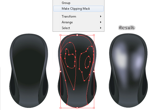
Now select and group (Ctrl +G) the four newly created shapes.
Next reselect the shape created in step 12, duplicate it once and then bring the copy to front (Ctrl +Shift +Right Square Bracket). Keep this copy selected, hold down the Shift and click on the new group, then go to the Object > Clipping Mask > Make (Ctrl +7).
Step 15
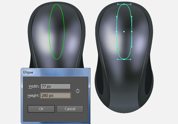
With the help of the Ellipse Tool (L) create a 77 by 280px object.
Next use the Direct Selection Tool (A) along with the Shift to increase the length of the handles of the top and bottom anchor points.
Step 16
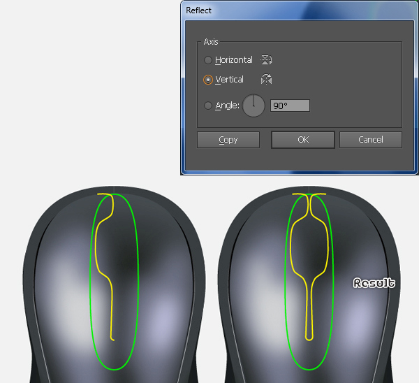
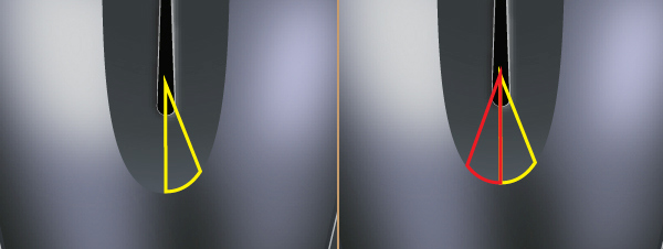
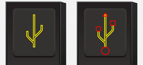
Using the Pen Tool (P) draw a yellow path as shown below. Once your path is drawn, reselect it and double-click on the Reflect Tool. In the Reflect box, check the Vertical and click Copy, then move the new path 30px to the right.
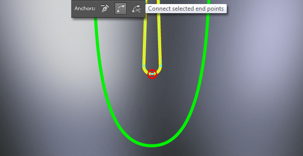
Reselect the two new paths, duplicate them once and then hide the copies. Now select the two bottom anchor points of the two remaining yellow paths and click on the "Connect selected end points" button from the Properties bar.
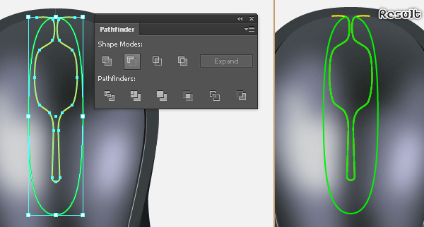
Reselect the new yellow path and duplicate it once. Keep the copy selected, hold down the Shift and click on the green object.
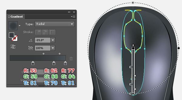
Next open the Pathfinder palette (Window > Pathfinder) and click on the Minus Front button. Finally fill the resulting object with the radial gradient as shown in the final image.
Step 17
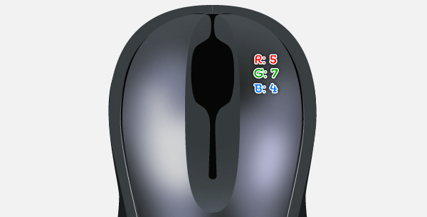
Select the remaining yellow object, bring it to front and then fill it with R=5, G=7, B=4 (stroke =None).
Step 18
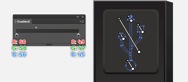
Press (Ctrl +Alt +3) to show the two yellow paths hidden in step 16.
Next select the two anchor points highlighted with green and remove them.
Now reselect the left path, fill it with none and add a 1px stroke (apply the linear gradient within stroke), then apply the Width Profile 1 for the result.
Select the remaining path, fill it with none and add a 1px stroke (apply the linear gradient within the stroke), then apply the Width Profile 2 for the result.
Step 19
With the help of the Pen Tool (P) create two objects and then fill them with the linear gradient as shown in the images below.
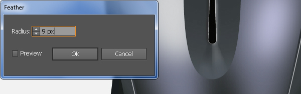
Reselect two new shapes and go to the Effect > Stylize > Feather… Enter a 9px Radius and click OK, then hide the resulting shapes behind the black shape.
Step 20
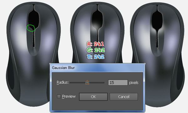
To add some details, first draw an object as shown below. Next fill it with R=241, G=242, B=242 and then apply a 15px Gaussian Blur effect for the resulting shape.
Make sure that the new shape is selected and double-click on the Reflect Tool. In the Reflect box, check the Vertical and click Copy, then move the new shape 30px to the right.
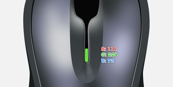
Next hide the two newly created shapes behind the black shape. Finally create another shape (R=111, G=224, B=72) as shown in the fourth image.
Step 21
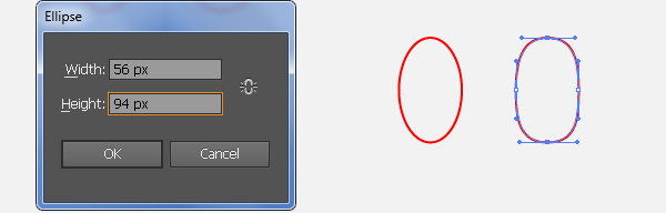
It’s time to draw the scroll wheel button. First draw a 56 by 94px object using the Ellipse Tool (L).
Next use the Direct Selection Tool (A) along with the Shift to increase the length of the handles of the top and bottom anchor points.
After you are done adjusting the shape of the new object, place it in the correct position as shown in the third image.
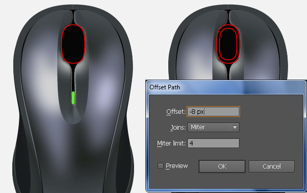
Keep this object selected, go to the Object > Path > Offset Path… Enter a -8px Offset and then click OK.
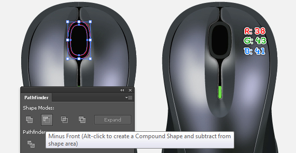
Now reselect the two new objects, open the Pathfinder palette (Window > Pathfinder) and click on the Minus Front button, then fill the resulting object with R=38, G=43, B=41.
Step 22
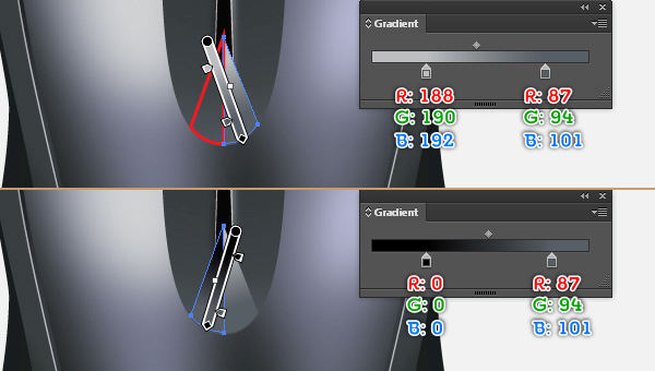
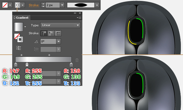
To give a more realistic look I’m going to be adding some highlights on the new shape. With the Pen Tool (P) draw two curved paths as shown below. Once your paths are drawn, select the left path, fill it with none and add a 2px stroke (apply the linear gradient within the stroke), then apply the Width Profile 1 for the result.
Reselect the remaining path, pick the Eyedropper Tool (I) and click on the left path. Keep the resulting path, go to the Gradient palette and move the center gradient stop to the right.
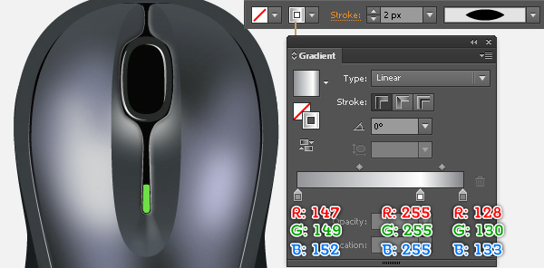
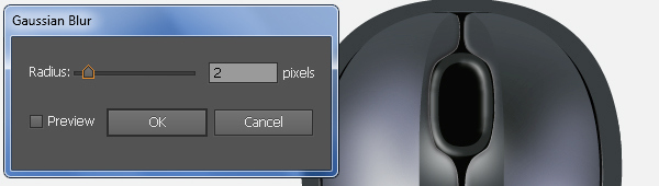
Now select the two newly create paths and apply a 2px Gaussian Blur effect on them.
Step 23
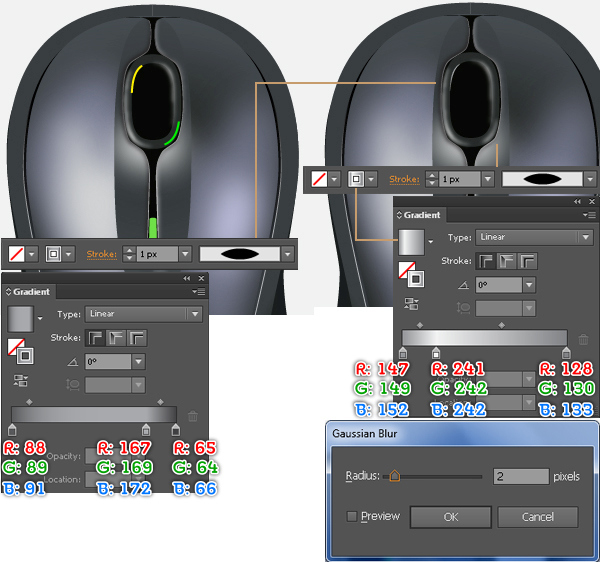
Continue with the Pen Tool (P) create two curved paths as shown below. Fill the yellow path with none and add a 1px stroke (apply the linear gradient within the stroke), then apply the Width Profile 1 for the result.
Next fill the remaining path with none and add a 1px stroke (apply the linear gradient within the stroke), then apply the Width Profile 1 and a 2px Gaussian Blur effect for the result.
Step 24
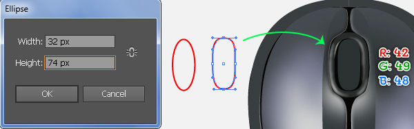
With the Ellipse Tool (L) create a 32 by 74px object. Next use the Direct Selection Tool (A) along with the Shift to increase the length of the handles of the top and bottom anchor points.
After you are done adjusting the shape of the new object, fill it with R=42, G=49, B=48 and then place the resulting shape to the correct position as shown below.
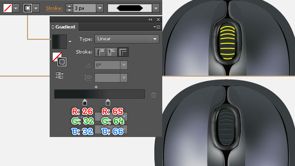
To add some details, use the Pen Tool (P) to draw some yellow paths. Once your paths are drawn, fill them with none and add a 3px stroke (apply the linear gradient across stroke), then apply the Width Profile 3 for the results.
Step 25
Now we are going to start making highlights on the scroll wheel button. First draw two curved paths as you see in the image below.
Next fill these paths with none and add a 3px stroke (apply radial gradient within stroke), then apply the Width Profile 1 and a 3px Gaussian Blur effect for the results. At this point your computer mouse should look like that in the third image.
Step 26
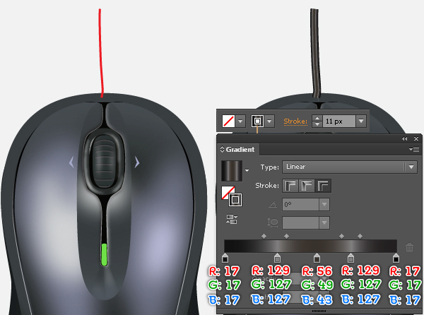
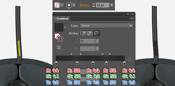
Next comes the cord. Pick the Pencil Tool (N) and draw a path as shown below. Fill this path with none and add a 11px stroke (apply the linear gradient across the stroke).
Continue to create another path as you see in the second image. Once your path is drawn, reselect it, pick the Eyedropper Tool (I) and click on the longer path, then change the color of the gradient stops of this path as shown in the second image.

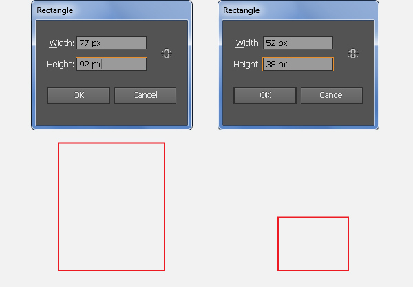
Step 27
Let’s work on the creation of the USB cable. With the help of the Rectangle Tool (M) create two objects with dimensions: 77px by 92px and 52px by 38px.
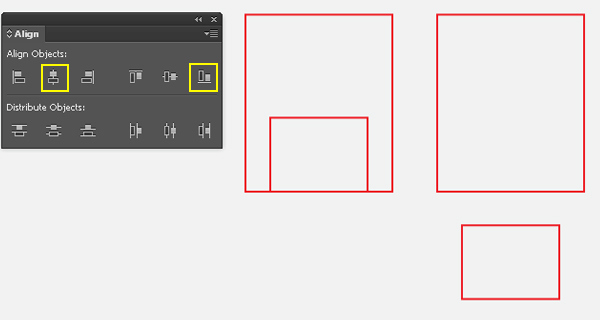
Reselect the two new rectangles, open the Align palette (Window > Align), click on the Horizontal Align Center button and then click on the Vertical Align Bottom button.
Next move the small rectangle 56px down.
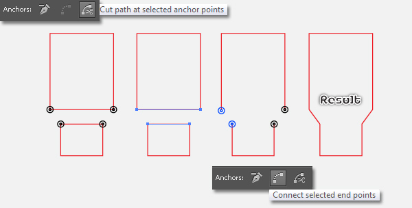
Step 28
Select the four anchor points highlighted with black and click on the "Cut path at selected anchor points" button from the Properties bar, then remove the two horizontal paths.
Next select the two anchor points highlighted with green and click on the "Connect selected end points" button from the Properties bar. Do the same, connect two anchor points highlighted with black.
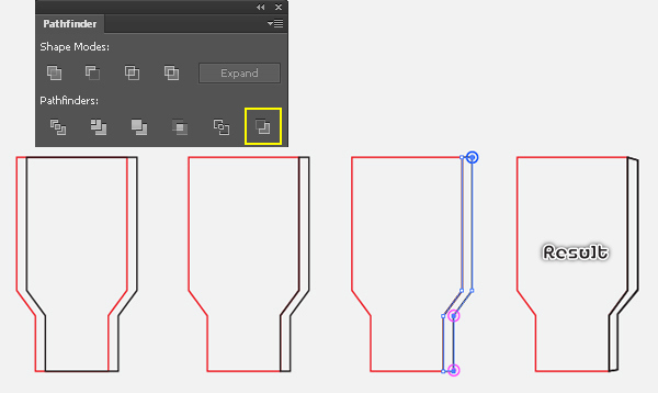
Step 29
Duplicate (Ctrl +C, Ctrl +F, Ctrl +F) the new object twice and then move a copy 7px to the right.
Reselect the two newly created objects and click on the Minus Back button from the Pathfinder palette.
Next select the top-right anchor point of the new object and move it 2px down.
Continue to select the two anchor points highlighted with magenta, move them 1px up and 1px to the left.
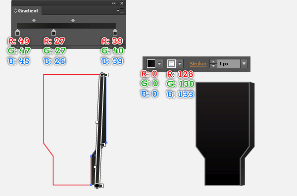
Step 30
Fill the black object with the linear gradient.
Next fill the red object with R=0, G=0, B=0 and add a 1px stroke (R=128, G=130, B=133).
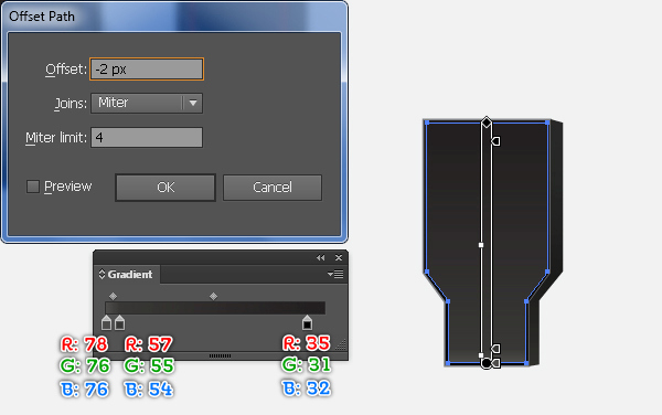
Keep the resulting shape selected, go to the Object > Path > Offset Path… Enter a -2px Offset and then click OK.
Replace the existing fill color of the new shape with the linear gradient as shown in the third image and remove the stroke.
Step 31
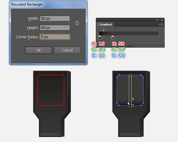
Double-click on the Rounded Rectangle Tool from the Tool palette. In the Rounded Rectangle box, enter the data as you see in the image below and click OK, then fill the new object with the linear gradient.
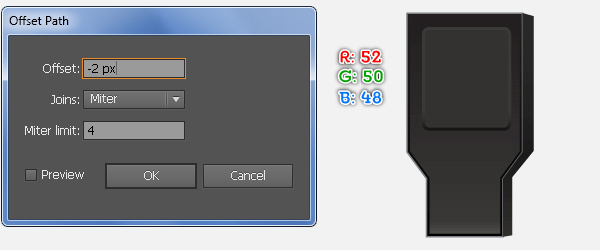
Make sure that the resulting shape is still selected, go to the Object > Path > Offset Path… Enter a -2px Offset and click OK, then replace the existing color of the new shape with R=52, G=50, B=48.
Step 32
To add some details on the USB cable, first draw some objects as you see in the images below.
Once your objects are drawn, fill them with the linear gradient as shown in the third image.
Step 33
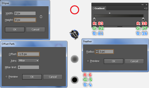
Continue to create a 8 by 8px object using the Ellipse Tool (L). Fill this ellipse with the linear gradient and then apply a 3px Feather effect for the resulting shape.
Keep the result selected, go to the Object > Path > Offset Path… Enter a -1.5px Offset and then click OK.
Replace the existing color of the new shape with R=6, G=5, B=4 and go to the Appearance palette (Window > Appearance), then remove the Feather section.
Next group (Ctrl +G) the two new shapes and make a copy of this group, then place these groups to the positions as shown in the final image.
Step 34
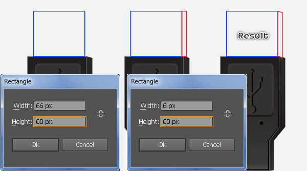
With the help of the Rectangle Tool (M) create two objects with dimensions: 66px by 60px and 6px by 60px.
Next place these rectangles in the correct positions as you see in the second image.
Now select the top-right and bottom-right anchor points of the red object and then move them 2px down.
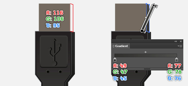
Reselect the blue object and fill it with R=116, G=106, B=95.
Next select the red object and fill it with the linear gradient.
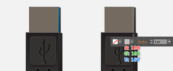
Continue to create two vertical paths as shown in the sixth image and fill them with none, then add a 1px stroke (R=198, G=191, B=187).
Step 35
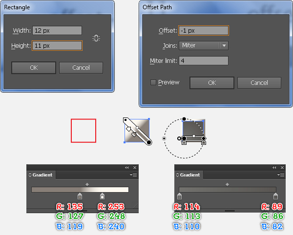
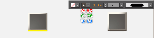
Using the Rectangle Tool (M) create a 12 by 11px object and then fill this rectangle with the linear gradient.
Keep the resulting shape selected, go to the Object > Path > Offset Path… Enter a -1px Offset and click OK, then replace the existing color of the new shape with the radial gradient.
Next create a horizontal path as shown in the fourth image. Once your path is drawn, fill it with none and add a 1px stroke (R=85, G=76, B=68), then apply the Width Profile 3 for the result.
Now group (Ctrl +G) all shapes created in this step and make a copy of this group, then place the two newly created groups in the positions as you see in the final image.

Step 36
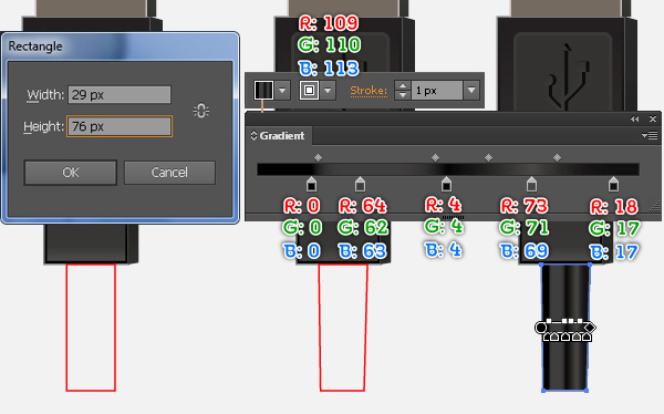
With the Rectangle Tool (M) create a 29 by 76px object. Fill this rectangle with the linear gradient and add a 1px stroke (R=109, G=110, B=113).
Step 37
Using the Pen Tool (P) create an object as shown below.
Make a copy of this object and then place the copy in the position as you see in the second image.
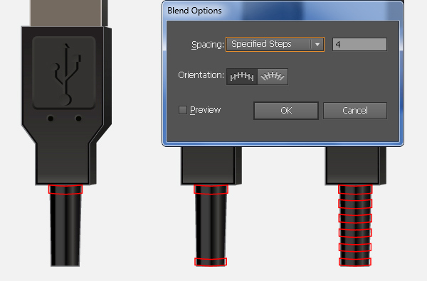
Now select the two newly created objects and go to the Object > Blend > Blend Options… Follow the data as shown in the third image and click OK, then go to the Object > Blend > Make (Ctrl +Alt +B).
Keep the result selected, go to the Object > Expand and click OK when the Expand box appears, then ungroup the result.
Step 38
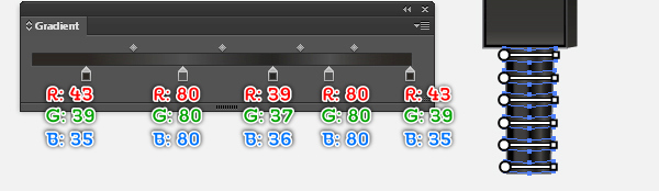
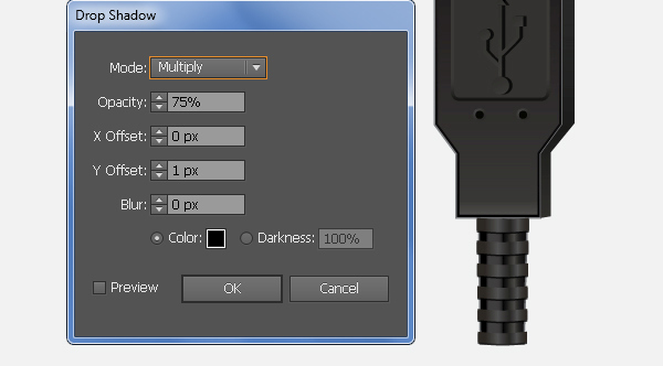
Fill the newly created objects with the linear gradient as in the image.
Make sure that the resulting shapes are still selected, go to the Effect > Stylize > Drop Shadow… Follow the data as shown in the second image and click OK.
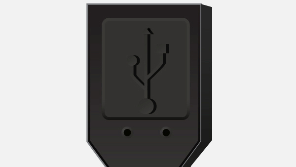
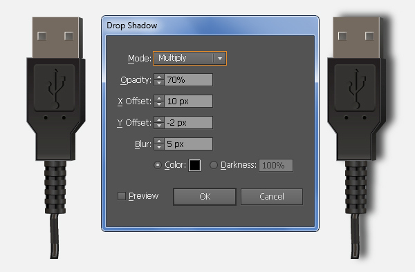
Now select and group (Ctrl + G) all shapes created from the beginning of step 27 to this time, then go to the Effect > Stylize > Drop Shadow… Follow the data as shown in the third image and click OK.
Step 39
Place the "USB_Cable" group in the position as shown below. Next select the "USB_Cable" and "Computer_Mouse" groups and then go to the Object > Transform > Rotate… Enter a -45 degrees Angle and then click OK.
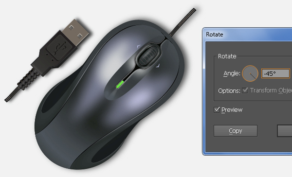
And We’re Done!
